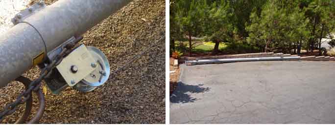
8/30/04 - tower arrives at Charlie's
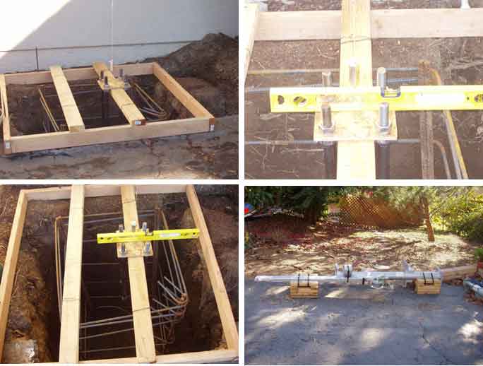
Digging the hole and making preparations for the tower base


Progress being made on 11/14-15/04
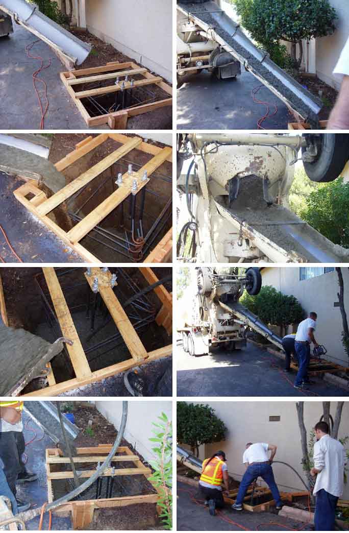
The cement pour - 11/17/04
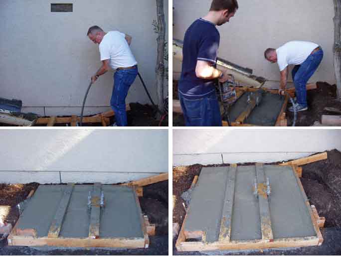
The tower base, and the raising fixture are now in place and level. I now have to wait for the curing to complete.
I may have a further delay since I am supposed to fill the foundation between the base plate and the concrete with 6000 psi grout. Not easy to find for a private buyer, as most goes to large scale construction. One place that does have it is closed for the holidays. I am told that the grout also needs 28 days curing time.
So, I may have an added delay to contend with. 73 de NN3V ...-.-

This is where the real "OOPS" series begins. In NN3V, Charlie's own words...
"Ah Yes: The technology center triumphs again! KF6WTN and N5AAA joined me today in what was to be a wonderful learning experience. As the attached photos show, we moved the tower into place without a hitch. It went almost too easily."

I am sure that our old friend Murphy saw Charlie having entirely too much fun! Again, in Charlie's words, here is what followed:
"And then Murphy waltzed in to the event. Turns out that the tower I bought second hand (and brand new) is 3/16" too large to fit into the base!!!!
Needless to say, we were all stunned. And while KF6WTN and N5AAA laughed in merriment, I sat next to the tower and picked my nose wondering what to do next.............. :=)) Our speculation is that the tower I bought - while never used and in pristine shape - may be a discontinued model from U.S. Tower (the paperwork with the tower confirms it to be a U.S. Tower)! The diameter of the tower exceeds the base holding fixture by 3/16". And of course, it will not fit into the harness points further up from the base.
So, on Monday I will be contacting U.S. Tower to find out why the mismatch. The previous buyer's name is still attached on the U.S. Tower shipping documents that were part of the tower paperwork, so I am sure they will be able to tell me what the reason is for the mismatch."

"Stay tuned for further tower adventures with Charlie!"
Hold your hats guys!
NN3V is not the VP of the Technology Center for nothing.
As you may remember, the tower I bought was (is) BRAND NEW. It sill has the original shipping documents attached, along with the metal bands that hold the cable supports to the tower during shipment. The shipping documents show the invoice number, and name of address of the buyer, from whom I bought the tower.
So on Monday I called U. S. Tower, played dumb and told the lady who answered that I was the original buyer, and needed to verify the tower model they sent me. Hee Hee Hee. She went off, and came right back to say that the tower was an MA-550. Just as the previous owner told me.
I hung up and called the guy who runs the tech support, and explained to him that the tower I had was a MA-550, and wanted to verify that the base and raising fixture I bought were indeed the MA-550B that went with the MA-550 tower. He assured me they were.
I explained the situation to him, and his immediate reaction was "DUH?" "You must have a different tower". I told him to go check the tower that was sold to the original owner, and a few minutes later he came back and agreed that the tower was indeed an MA-550 and that he was unable to explain the cause of this screw up. He also verified that the tower was purchased in fall 2003, so we both agreed it is a new tower, especially given the condition of the tower with brandy new nameplate, etc., etc.
He called back today to inform me that they determined the foundry they use changed the tubing of the tower and did not notify them that there was a change. In essence, at least in professional manufacturing processes like we use in the defense industry, the towers they are selling today should be called something like MA-550.1, or MA-550A, or something like that. Same goes for the base since that is now manufactured to the new dimensions.
U. S. Tower seems willing to make good. The only issue is how they will do so. They began by suggesting they would manufacture a new base for me that fit the old tower dimension. I told them that with the base already erected and cemented in place, I had little desire to bust the grout, probably ruin the bolts, and try to remount a new base. That I preferred they take the tower back, and send me a replacement tower. To a certain degree, they are over a barrel since they have a defective product line that would have gone completely unnoticed had it not been for the strange circumstance that I bought a brand new discontinued line that is nomenclatured the same as the new product. A screw up on their part.
So they could save some face, I mentioned that I have a buyer for the tower in my yard, who will buy the tower if they sell him a base that fits the tower (I suppose one would call that an old specification base). That way they would make some money on the base sale, and all I wanted was for them to send me a new tower to the new dimensions that fit the base they sent me.
The gent I spoke with told me he would bring this proposal up to the owner of U. S. Tower and get back to me.
Stay tuned !!
:=)) :=)) :=))
73 de NN3V ...-.-
Well, the tower may be on hold for a bit. But that does not mean the antenna needs to stand idle!
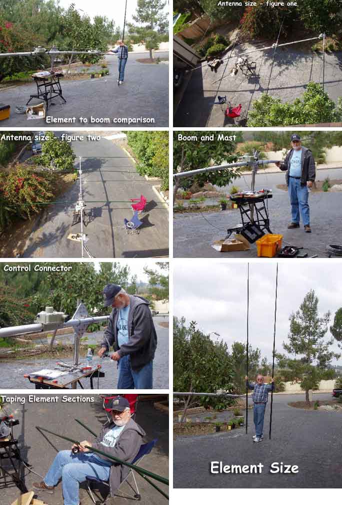
Herewith the first group of SteppIR up-close photos.
The boom is 36' long, and holds 4 stepper motor housings. Each housing has a control cable attached, and the control cables mate up to a control harness that leads down to the control head of the SteppIR system inside the shack. There is a photo of the steppIR controller included as well.
On one side of one of the stepper motor housings you can see inside the element cavity, and see a little hole. Inside that hole is the extendable metal element that "shoots out inside the element". When I assemble the antenna you will see the elements are green fiberglass tubes that allow the metal element to extend and retract inside the tube.
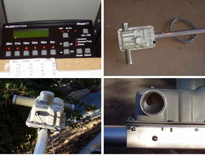
73 de NN3V ...-.-
February 13, 2005
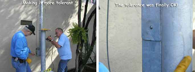
Well, here is the rest of the story. The day before St. Valentine's, John (N5AAA) and I proceeded to raise the tower. The work required some careful preparation. The new base arrived, and was inspected first of all to make sure the base finally was the correct one. It was.
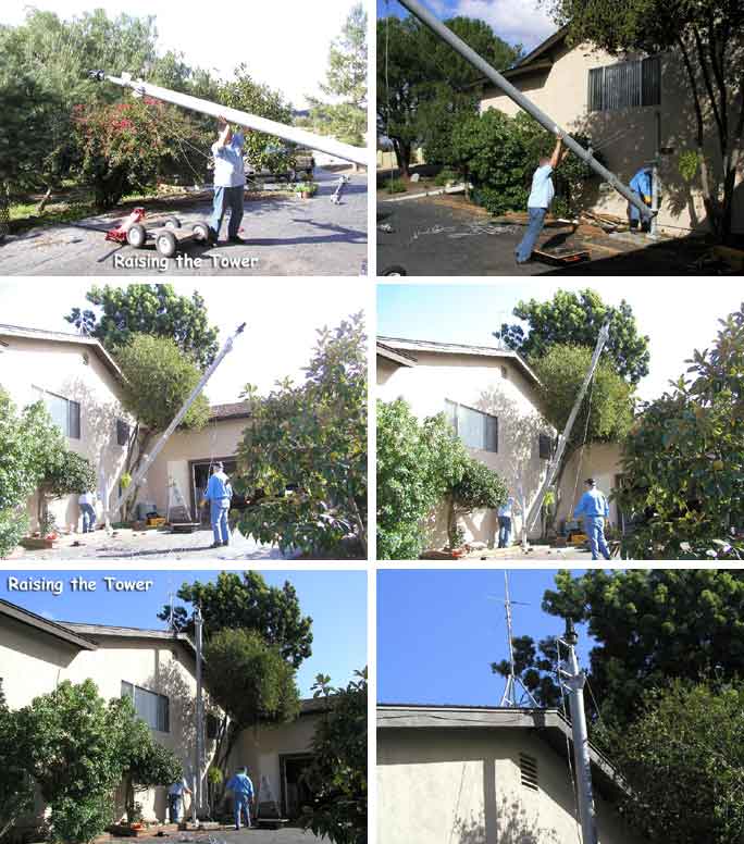
The photos show the level check, and then we attached the raising fixture (gin pole more or less). Surprise, the U. S. Tower manufacturing was slightly off tolerance, and we couldn't find the hole! Not to worry, the Technology Center approached the task and made the hole bigger. There were some tolerance issues that arose, mostly as the hired help failed to watch carefully how the Technology Center director desired to tighten the bolts in the correct manner. A short side discussion on who was in charge took care of that problem.

Supervision of the attachments to raise the tower was in the hands of a fine looking YL who made sure the hired help kept on task and did not deviate from the chosen steps in the raising of the tower. The raising was a piece of cake, thanks to the fine art of "manuel" power.

Sunday, 2/27/05
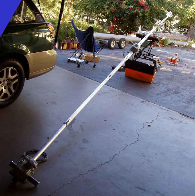
John and I joined forces on Sunday to assemble and test the antenna on the ground. This was suggested by KJ6RA as a way of avoiding a nasty surprise once the antenna is up on the tower. We had quite a surprise once all the boom pieces were together, as little did we realize how long 34' are! Assembling the antenna on the ground allowed careful preparation of the boom elements, all telescoping fiberglass tubes that once pulled out to length are then taped for water protection. The hired help performed this task with excellence, allowing fast progress.
The Fluid Motion antenna instructions indicate that when one first turns on the controller, it is important to make sure the controller is in the "elements retracted" position, as that is the way the antenna is shipped. When you look at the photos you will see some gray boxes on the boom. Each box contains two phosphor bronze "tape measures", and they are extended and retracted by the stepper motors that are inside the gray boxes.
The controller senses the antenna SWR on the antenna. The controller also has 6 separate positions for 20M through 6 M. Each position is pre-calibrated with 52 positions that were set at the factory for an antenna up at 45 feet. So either your antenna will automatically match the 1.0 SWR calibrated at the factory, or the controller will adjust the element length based on the SWR it senses at your antenna's location.
The phosphor bronze "tape measures" slide in and out inside the green fiberglass antenna elements you will also see in the photos.
Following the recommendations of KJ6RA, the SteppIR controller and elements were exercised on the ground to ensure that all worked as designed. FLAWLESS!
We plan on raising the antenna to the tower rotator this Thursday.
73 de NN3V ...-.-
Thursday, March 3, 2005
We then raised the boom to the roof, climbing the roof from the back of the house. At that point, the roof is only 12' above ground, so the boom was placed next to the house, one of us climbed the roof, pulled on the boom while the other pushed, and without any effort at all the boom then slid onto the roof. It was then placed lengthwise adjacent to the tower, the mast piece was inserted in the attachment fixture, and we walked the boom out over the rotator. At this time there were no cross elements on the boom. When the boom alone had the mast over the rotator, we inserted same into the rotator, sat down and clamped the rotator onto the boom.
After that we simply rotated the boom so that we were able to attach the fiberglass elements into the boom while we sat on the roof. Once all the fiberglass elements were on the boom we activated the controller to extend the phosphor bronze elements inside the fiberglass tubes, called Hoss (WA5ZAI in Valley Mills, Texas), and had a 5x9 + 20 contact (SWR of 1.0) running 50 watts from Poway, CA.!!!


The end result is a thing of beauty,
The superior technology built into the Yaesu Mark V Field is now matched to the superior technology of the SteppIR, resulting in one hell of a fine station.
One of the photos attached shows the result of planning the work, and then working the plan, as the idea was to end such that when the tower was retracted to it's lowest height (22'), the antenna elements clear the fireplace chimney. The plan was for a 12" clearance above the chimney. The measured result is 9" clearance!! At the rear of the photo the trusty R7000 vertical can be seen, reminding me that the sage comment of WA5ZAI came true. A million dollar station backed up by a $2.00 antenna (the R7000) just makes for a $2.00 station!!
73 de NN3V ...-.-
![]()